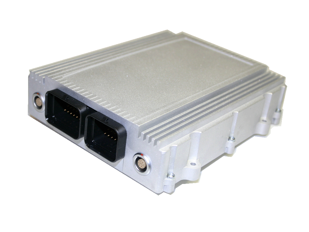
The MCS400EC is a fully customizable ECU for advanced research
and development, and it is capable of controlling injectors /
ignitions up to 12 cylinders together with the breakthrough
feature called
crank analyzer.
The MCS400EC is loaded with already known features and
functions of MCS400 series such as powerful DriveRecorder.
Virtually any number of signals from any source can be stored
into a circular buffer of up to 16 GB size at speeds of 10 MB/s.
The circular buffer can be emptied at
any time - even while the recording is in progress, to allow
data recordings without gaps over very long periods. Retrieval
of recorded data over LAN or USB2.0 is at speeds of 300 MB/minute. Smart on-the-fly data processing allows previews of
the entire recording to be uploaded in seconds. The recorder
is fail-safe even in case of power loss and is auto-resuming
when power returns. |
 |
With the
I/O-Interfaces an external analog and/or digital data
aquisition is possible. If you use the digital-input for the
crank-position you could analyze the datas by the internal
crank analyzer. Or you use them to work with the Rapid
Prototyping as you know it form the former MCS4/MCS400 with
MATLAB/Simulink
®. It is possible to get a Development
Environment with up to 20 inputs/outputs free of charge.
Built around the Freescale
MPC5200, the MCS5 delivers a performance of 760 MIPS
(million instructions per second) . The on-chip double
precision FPU and the proven, robust VxWorks 5.5 RTOS make
the platform ideally suited for running
Rapid Prototyping applications concurrently with it's system
tasks.
|
|
|
Technical Data |
|
• 2 x 400 MHz Freescale MPC5200 PowerPC delivering 760 MIPS
• on-chip double precision Floating Point Unit, 128 MB RAM
• VxWorks 5.5 Real Time Operating System
• Dimensions (mm): Depends on customized configuration
• Temp. range: -40 to +85 °C operating
• Power Supply: 4V to 60V
• Power Dissipation: Depends on customized configuration
• Special enclosures, connectors and pin assignments are also
customizable. |
|
|
Interfaces to Host-PC |
|
• Ethernet 10/100
• USB 2.0 |
|
|
Interfaces to peripherals |
|
• Depends on customized configuration (either CAN 2.0B, or
other hispeed communication interface as follows)
|
|
Highspeed Interface to  |
|
• Uses the On Chip Debug Support (JTAG-OCDS)
• Very short downloadtimes
• Measure without problems of bandwidth
• Rapid Prototyping without latency
|
|
Highspeed Interface to  |
|
• Uses the AUD-Interface
• Very short downloadtimes
• Measure without problems of bandwidth
• Rapid Prototyping without latency
|
|
|
Options |
|
• Fully customizable
|
|
|
I/O Peripherals (an example for minimum configuration) |
|
•
4 x
ignition drive (Max. 300mA)
•
8 x
injection drive
(Max.2.2A / 70V)
•
16 x
1kSps analog inputs
16bits (3.3V/5V)
• 8 x Analog Inputs 0..5V, 12 Bits (up to 100kSps or
vs. crank angle at 0.5° resolution)
• 8 x Digital 3.3V/5V bidirectional (up to 10MHz or vs. crank
angle at 0.05° resolution)
•
2 x
Thermo couple
•
3 x
Hi-Bridge DC servomotor output (Max.
7A)
•
8 x
standard power output
(Low
side,Max.
2.2A)
• shaft speed sensing (crank, cam, ...) by inductive
pick-up or DHE |
|
|
DriveRecorder |
|
|
• High Speed 1GB Flash Drive (optional: 16GB; 8GB linear, 4GB ring buffer, 4GB user Network drive) |
|
|
Network Functionality |
|
• DHCP server or fixed IP Address Support
• Auto MDI / MDIX crossover select |
|
| CAN,
CCP and XCP Functionality (when CAN interface is selected as
an communication interface) |
|
• ECU Calibration & data acquisition over CCP and XCP (up to
20 ECUs simultaneously)
• ECU Flash programming over CCP and XCP
• CAN data acquisition & bus monitoring
• CAN bus termination software selectable |
|
|
Cost |
|
|
Please contact
us in order to receive a quote. |


